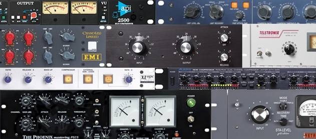
How Compressors Work
Making a Scene Presents How Compressors Work
The best way to learn how to use a compressor is to start by learning how they work. This article is setup to bring you step by step through how a compressor works. I have included some video tutorials along the way that I found to help you understand the concepts. Take your time and and make sure you understand each section before you move on to the next. If you have to, google more resources on that section, until you fully understand it. If you do this, the next time you pull up your compressor, whether it’s hardware or software, you will have a completely new view of your compressor and a whole new understanding on how to best use it will present itself to you.
History
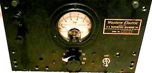
Back in the early days of radio broadcasting the radio engineers had to ride the microphone volume to protect the signal from over modulation, which could distort and possibly take the signal offline. In 1937 Western Electric came out with the 110 Limiting Amplifier and the world of audio compression was born. When the engineers from radio started to bring their craft to the recording studio, they brought their compressors with them. It allowed them to control the dynamic range of the audio signals that defined the “Radio Sound” to the direct to disk recording and later to tape. Those early compressors had little in the way of controls. The min and max settings were set and those early units just were input/output devices.
How They Work
The compressor is, at it’s core, a device to limit the dynamic range of an audio signal. It makes loud sources softer and soft sources louder thereby reducing the “Dynamic Range” or the volume range between the softest and loudest part of an audio signal. This is accomplished by a circuit called a “Unity Gain Amplifier”.
Now the term amplifier is a bit of stretch for this type of circuit, in that the input signal is at the same level as the output signal. The defining aspect of this type of Amplifier is the “Feedback” loop where input signal is used to control the volume output. The louder the input signal gets, it is feed back into the amplifier circuit where it lowers the output. Consequently when the input signal is low the output signal is allowed to be louder.
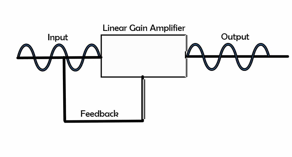
Now there are many different types of “Linear Gain Amplifiers” which go a long way to create the “Color” any compressor. They can be made up of a variety of Tubes, Transformers, Transistors, IC Circuits, etc. But the main function of the compressor and which one you decide to use, is determined by how the gain reduction is controlled. Let’s take a look at the 4 styles of compressors and how they control the Dynamic Range of the signal.
FET
The FET or “Field Effect Transistor” uses a transistor to control the gain reduction circuit. A transistor is part of the amplifier circuit where the signal moves from the “Emitter” to the “Collector” and the Source signal from the emitter side is also sent to the “Base” of the transistor. The more signal that appears at the base, the less signal is allow to pass through the amplifier. This is how gain reduction is achieved. (see video below on how a transistor works)
The advantages of FET compressors are:
- They are relatively inexpensive
- They generate very little heat
- They are small and you can put many of them in a small space
- They have a very fast response time
These attributes make the FET great for high transits sources like drums, acoustic guitars and even vocals. They can also introduce a variety of “Harmonic Distortion” that can give your source a full, lively feel.
One of the most famous FET type compressor is the Iconic Universal Audio 1176 Type compressor

[amazon_link asins=’B078SVZ11X,B07G8NSWXY,B00K2T2FGG,B014HDIBFQ,B003ZZQC40,B00MHWAE5A’ template=’ProductCarousel’ store=’maasc-20′ marketplace=’US’ link_id=’80aedc15-e027-41b7-8e2f-b33f781ee9cf’]
Optical Compressors
The next type of compressor uses an “LED” or Light Emitting Diode and a photo resistor. As the light source gets brighter (or the signal gets louder) the resistance becomes greater thereby reduces the gain of the amplifier. (see Video Below on how Photoresistors work).
The main attributes of a Optical Compressor are:
- They are relatively slow to respond to signal changes
- The feedback circuit is effectively isolated from the circuit which makes these very clean sounding
These are commonly used for Vocals, guitars, even drums.
The most famous of these compressors is the Teletronics LA2A
[amazon_link asins=’B01J3Y7TNO,B00Y3Q6BE6,B0012MIVW4,B01DD2AALA,B01DXL7DUC,B07CWTF6XT,B003J7THLY,B001F71WZO’ template=’ProductCarousel’ store=’maasc-20′ marketplace=’US’ link_id=’2027c459-c261-44f4-9360-0dfd35335351′]
Variable MU
The Variable MU compressor is a tube based compressor where “MU”, in the tube world, means gain. Tubes work very much like transistors work. Instead of an emitter, collector and base, you have a Anode, Grid and a Cathode. The signal flows from the Cathode through the Grid to the Anode. The “Bias” or signal you apply to the grid will control the amount of signal that is flowing through the circuit. The more voltage at the grid, the less the flow you have moving from the Cathode to the Anode of the tube, thus more gain reduction. (see the Video Below on How a Tube works)
These are by far the most rare of the compressor circuits out there. The most famous of these is the Fairlight 670 compressor. The bottom line if and I say if you can find one, the cost would be more than a luxury car!
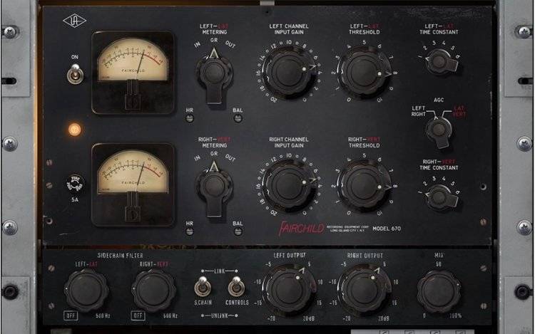
These compressors are most often used in the mastering process because of their warm analog sound and response. They are often placed at the output of the master buss as “Glue” for the mix.
[amazon_link asins=’B004X7HV4Y,B01I03JGNK,B01DZCF14Y,B01DZAPH8G,B004X7HV9Y,B0053T0616,B003BQ8GB0,B01DXNKFS2,B00YVV0NMO’ template=’ProductCarousel’ store=’maasc-20′ marketplace=’US’ link_id=’f640685c-634f-4db6-891b-d5f72f0e9b42′]
VCA
The VCA or “Voltage Controlled Amplifier” works much like the FET compressor with the only difference being, instead of a transistor circuit controlling the feedback of the circuit, the transistor involved is part of an integrated Circuit Chip or “IC”. An Integrated chip is the basis of all modern electronics where it has many transistors built into a relative small footprint. These compressors are very fast and small! Because of this they are used in many of the compressor circuits in channel strips and mixers. If your compressor does not specifically state it is FET, Optical or Variable MU, it is more than likely a VCA Compressor.
One of the famous VCA style Compressors is the DBX 160 Compressor
[amazon_link asins=’B0002H0QGE,B001N0LI3Y,B0002ORP98,B00U2L0Q2Y’ template=’ProductCarousel’ store=’maasc-20′ marketplace=’US’ link_id=’d1cc11f8-a985-477f-8ae0-18300c2c4f4d’]
Threshold, Attack, Release, Ratio and Makeup Gain
Now that we have an understanding on how different compressors reduce the dynamic range, we need to look at some of the other controls on the compressor to understand how they work within that circuit to achieve gain reduction.
Threshold
Simply put the threshold is where you set the level at which the “Gain Reduction” Circuit will kick in. Everything below the threshold you set will be at complete unity gain, or in other words, the compressor will have no affect on the signal. Setting a threshold so it only affects the transient peaks, will compress those peaks and leave the rest of the signal untouched. Setting the threshold so it encompasses the whole signal, it will have the effect of squashing the dynamic range of the whole signal.
Attack
The Attack of the compressor is how fast the compressor will react to the signal. A slow Attack will allow the initial transients to move through the compressor fairly untouched. Which means that a fast attack will allow the compressor to kick in quickly catching those transients and applying compression to them.
Release
Like attack, the release control on the compressor is also a time based setting. Instead of controlling the time the compressor begins compression, the release controls the time the compression circuit releases the compression.
Ratio
The Ratio is quite simply the amount of compression you want to apply to the signal. This amount is represented by a ratio of input to output. For example if you had a ratio of 2 to 1 that would mean for every 2DB of input that is above the threshold, you would only get 1DB at the output. This is the setting that determines how hard the compressor is working on the signal.
Makeup Gain
When you apply compression to your signal, you can lose it’s overall gain. Many compressors allow you to compensate for this loss of gain by give you a “Makeup Gain” or “Gain” that will boost the compressed signal to be equal to or exceed the level of the original input signal. The only difference is the dynamic range of this boosted signal now has a compressed dynamic range.
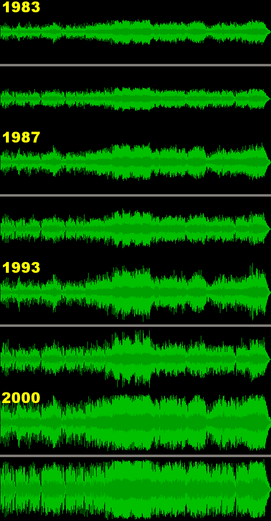
The Volume Wars
Over the course of it’s lifetime the compressor has also gotten a bad rap as the single tool most responsible for the “Volume Wars”. As we moved from Vinyl to Tape and then to CD’s the available Dynamic range has increased from 40db to 70db! Mastering engineers who worked in the world of Vinyl used compressors to keep the dynamic range and overall volume low enough that the needles did not just jump out of the grooves. By the time CD’s came about, this larger dynamic range also gave these new mastering engineers the ability to cram more “Volume” into that expanded dynamic range window. This was the beginning of the “Volume Wars”! Record companies wanted their artists to “Jump” out at you when their music was played on the radio or you put their CD in your player. The mentality was if their music was louder than the song before it, it would grab your attention. Many think this has had an adverse effect on recorded music. Rather than using the expanded Dynamic Range in the CD/Digital world to expand the subtle nuances of music, it has been used to over compress the dynamic range and using makeup gain to fill up the available dynamic range of the medium with pure volume, instead of musical subtleties.
Conclusion
There are a few more aspects of the compressor you should explore such as the Hard and Soft Knee, Side Chaining, Hold Time, etc. But this tutorial will give you the knowledge you need to start understanding how a compressor works and how you can best use it for your recordings.
Discover more from Making A Scene!
Subscribe to get the latest posts sent to your email.

